Monday, February 27, 2017

Wheels and Tires

After resolving all of the design challenges involved in making a car, the choice of wheels and tires may seem like an afterthought. But in fact, they are both essential to the car's performance, and are usually considered early on in the design process.

It's also surprising how many key dimensions there are in the wheel/tire setup. For this, I'll reference a diagram from H-Point.


Most of these are self-evident. Tire crush (bottom left) is important when setting up the spindle location. If any part of the car is extremely close to the ground (like on a race car) then a little added weight could compress the tire and cause scraping on the ground, which is not good. The static load radius (SLR) solves this problem. This is a measurement of the tire radius with the occupant and maximum cargo load. The SLR determines the wheel\tire position relative to the car, because the spindle (with the rest of the car) will not get any lower than this. Thus scraping will cannot happen.

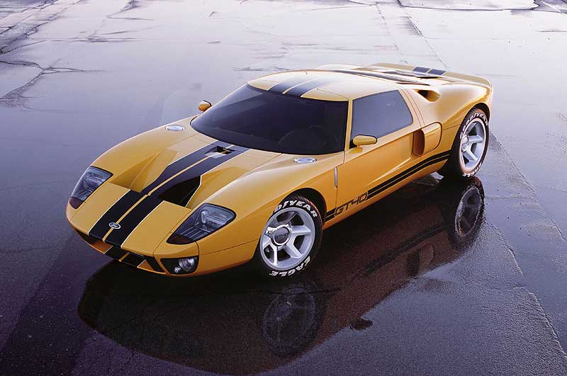
Form and function go hand in hand, so vehicles with different objectives need differently shaped wheels and tires. Trucks and SUVs have a large tire profile (aka sidewall) height to increase cargo-carrying ability (Gross Vehicle Weight, or GVW) and protect the wheels on rocky ground. This will also improve the ride comfort, because the large tires act as a cushion. However, this cushioning effect is caused by sidewall flex, in which the tire bends a little out of shape. This drastically hurts handling. Passenger cars maintain a balance between comfort and handling, Thus, these vehicles have a larger wheel and smaller tire profile. In sports cars, handling and cornering ability cannot be compromised. This requires a small tire profile to minimize sidewall flex during cornering, resulting in a larger wheel. The larger wheel also allows for a larger brake rotor, which improves braking ability. On the other hand, the larger wheel increases the combined weight of tire and wheel, which counteracts the handling benefits.

Passenger cars and light trucks have completely different tire specification methods. Lets look at an example of the former:

P 215 50 R 16

The first letter just specifies that it is for a passenger car; simple enough.

The second value is the tread width in millimeters.

The third is the sidewall aspect ratio. This is essentially the tire profile height represented as a percentage of the tread width. In this example, the profile height is 50% of 215, the tread width.

The fourth is the speed rating (not essential).

The last value is the diameter of the wheel rim.

Using these three numbers, we can determine the outside diameter of the tire.

(in millimeters) (215 x 50% x 2) + (16 x 25.4)

The first product yields tire profile, multiplied by 2 to account for the sidewall on both sides of the wheel. The second product is just a conversion from inches to millimeters. Together this adds up to the total diameter of the tire.

Thanks for reading!

Saturday, February 25, 2017

Powertrains

Finally, it's time to discuss the most important part of the automobile--the part that banished the horse-and-buggy to the history books. Of course, I am talking about the engine.

There are many different engine setups, each with their own set of advantages and drawbacks. We will explore these in a moment, but first we need to understand the system that the engine is part of, the powertrain.

Here is a visual representation of the powertrain from H-Point.


First of all, there is the engine. Conventional internal combustion engines (ICE) react fuel with oxygen to release energy that is transmitted to the wheels.

This process, naturally, starts with the transmission. Attached to the end of the engine, it can deliver power at various speeds. To do this, a clutch or torque converter is positioned between the engine and the transmission for manual or automatic transmission, respectively.

Final Drive is the series of shafts and gears that connects the transmission with the wheels, giving them power to turn.

No machine is 100% energy efficient. Unused energy is released in the form of heat, which is what makes engines hot during use. Cooling modules prevent the engine and other systems from overheating. They are placed where cool, moving air is easy to access.

The fuel tank's capacity depends on the size and intended range of the vehicle. The most important consideration is placing the fuel tank somewhere safe in case of a collision.    

The combustion reaction that occurs in the engine produces H2O and CO2. These gases must be removed so that fresh air can enter the engine. The exhaust system expels these products.

Electric Powertrains come in two forms: Battery and Fuel Cell (FC). Batteries store electrical energy while fuel cells generate it using compressed hydrogen gas.

Both use a battery, but the FC system's is a smaller, supplementary energy source.

The FC system has hydrogen storage tanks that feed the fuel cell stack.

Both systems use an electronic converter to control the amount of energy given to the motors.

Electric motors are small and powerful, which allows for easy packaging on the axle or even the individual wheels.

There is also no need for a transmission like in the ICE. However, the fuel storage tanks and batteries are much larger than a conventional fuel tank. They are usually positioned under the floor, which saves space and creates new design possibilities.

There are two ways to position a conventional engine: longitudinal and transverse.

In longitudinal engines, the output shaft is parallel to the vehicle (front-back), while in transverse engines, the output shaft is perpendicular.

Transverse engines save space, but are constrained by the width of the frame rails.
Longitudinal engines take up more space but allow for larger engines to be installed between the frame rails.

Below are all of the possible engine configurations and some examples. Notice how the placement of the engine affects the architecture.

Front engines are positioned beyond the vehicle's front spindle (the shaft that turns the wheels).

Mini Cooper
 Front mid-engines are located between the front spindle and the driver.

Dodge Viper


Rear mid-engines are located between the rear spindle and the driver.

Bugatti Veyron


Rear engines come after the vehicle's rear spindle.

Porsche 911

That's all for this week!

Wednesday, February 22, 2017

The Anatomy of a Manikin (yes, this has to do with cars)

Most of you have probably seen the crash test dummies used to test airbags and other crash safety systems. Automotive designers use a similar device, called a manikin. These aren't dragged out of an Old Navy, they have very specific geometries that reflect the body of a 95th percentile US male (97.5th percentile, including women). The Society of Automotive Engineers (SAE), with the help of other organizations, has collected data on the size, proportions, and movement of the human body to develop this manikin. Designers usually set up the interior space using the 95th percentile manikin to ensure that almost everyone can fit. This diagram from H-Point highlights all of the key features.


The most important part is the h-point, (hence the book's title) also called the seating reference point. This point's location determines the occupant's position relative to the vehicle. The lower the h-point, the lower the occupant is sitting and the further out his/her legs are stretched longitudinally. This relationship between the h-point and the rest of the body creates what is called the SAE accommodation curve, shown in the above diagram.

Notice how no matter where the h-point is on the curve, the feet stay almost in the same longitudinal position, with the torso and legs always in a natural sitting position. This is key when setting up the driver's height and posture. This curve does not apply to rear occupants, however, as their space is often constrained by the total length of the vehicle. This is because the vehicle's length is dependent on the couple distance, which is the horizontal distance between front and rear occupants' h-points. Thus, limits to the vehicle's length will impact rear occupants' space the most.

The following anatomical features are also important for establishing the occupant's environment.

The accelerator heel point is the lowest vertical point of the manikin. For this reason it is used to establish the floor and step-in height.

The ball of foot point is used to determine how much crush space is needed in front of the driver. As discussed in a previous post, crush space is the space  that will compress on impact between the occupants and the exterior surface of the car.

It is essential that every occupant, regardless of their size, has good visibility. For this, SAE developed the 95th percentile eye ellipse, within which 95% of drivers' eyes will be located. Using this ellipse, designers can position the windshield to ensure good visibility.  

Nobody wants a car that doesn't provide enough head room. Designers use the SAE 95th percentile head contours, a volume that represents the amount of head room a 95th percentile occupant needs. This also incorporates space needed for head movement and seat track movement.

Lastly, the thigh center-line is used to position the steering wheel.

That's all for now: up next is interior design!

Friday, February 17, 2017

Aside: Laser Cutting

The focus of my research is automobile design, but at CREATE I am also learning how to use the tools to produce my first vehicle. This week I learned how to use the laser cutter. This tool is used to engrave on a variety of materials or precisely cut materials into any shape. To make these shapes I learned to use CorelDRAW, a CAD program. I would have included video of the laser cutter in action, but the protective glass cover created way to much glare. Once I complete the body of my car, I can fit it with wheels made in the laser cutter. This way I can create my own design for the wheel covers. To create traction, I could even wrap rubber bands around the wheels. I can also place the car body inside the laser cutter to engrave designs on the hood, sides, roof, etc. For now, though, I will focus on designing the car!


Today is also my birthday (yay!) and an important step in completing my project.


My dad got me a book of classic sports cars. I will come back to this later for inspiration when designing my car.


I also got a new laptop for my birthday because my current computer did not satisfy the hefty system requirements of Autodesk Alias 2016, an automotive design tool I will be learning.


I will leave you this week with a few cars featured in my dad’s book, along with their modern counterpart.


Enjoy!

1978 BMW M1

BMW M1 Concept

1968 Ford GT

2017 Ford GT

Thursday, February 16, 2017

Getting Started

To create a feasible vehicle design I will need to read H-Point: The Fundamentals of Car Design and Packaging in its entirety. Thus, I will dedicate these blog posts to sharing knowledge from my readings so you can also walk away with an understanding of vehicle design.

So without further ado, let’s dive in!

Every vehicle comes with its own unique set of hardpoints. Hardpoints are features of the package that have specific constraints, based on the objective(s) of the vehicle and regulation requirements. I will use the following diagram from H-Point as a reference.


Here are some that I picked out: (numbers correspond to the diagram)

2) Front Wheel and Tire: The front wheel’s position depends on the position of the transmission’s output shaft (for front wheel drive vehicles) and the vehicle’s weight distribution. The tire envelope is determined by the jounce and turn of the wheel. Jounce is the vertical movement of the wheel as allowed by the suspension system. You do not want the top of the tire to hit the envelope. Similarly, the tire envelope must allow the wheel full motion when turning left and right.

3) Chin Height: Do you know what the height of a standard parking block is? Answer: 162mm. The “chin” of the car must clear this height at a recommended approach angle of 10 degrees. For off road vehicles, however, the recommended height jumps up to 28 degrees. This allows the vehicle to clear larger obstacles without damage to the exterior.

4) Front Bumper Location: In the event of a collision, the bumper must have enough crush space in front of the occupant’s feet. Rigid objects like the engine and steering rack increase the amount of crush space needed. There are also pedestrian safety laws that govern the shape of the front fascia. For example, the front of the car cannot be pointed like a rocket. Even if it improves the aerodynamics, that would hurt!

7) Cowl / Windshield Touch Down: This part of the car must provide enough room in front for engine maintenance and maintain good proximity between the driver and the controls. Also, the windshield should be no more than 25 degrees above horizontal, above which which the driver’s view is distorted due to refraction.

8) The header location should allow for adequate upward visibility, which is at least 11 degrees from horizontal.

18) Belt-line location: Designers must consider the height of the belt-line relative to the occupant to ensure the seat belt is comfortable and there is sufficient shoulder room.

19) Body Side Profile: It is important that the glass has enough room to drop inside the door’s outer profile, missing all of the hardware and side impact protection systems within the door. This puts constraints on the height of the side glass windows and the door. I have rolled my window down countless times but I never thought of where the glass went.

Certainly all of the hardpoints in the above diagram are essential to designing a car, but I wanted to give you a taste of automotive design with the ones that I found most interesting.

Thanks for reading!

-Alek


Saturday, February 11, 2017

One High Performance Car Coming Up!

The first step in creating a car is determining the vehicle type. This will focus the design in a specific direction based on the vehicle’s purpose. Usually, car manufacturers conduct market research before making this decision, but that does not apply to this project. Thus, I immediately decided to make a high performance car.

Pencil finally hits paper in the Design and Package Ideation stage. This involves only a handful of elements, drawn in broad strokes. Here are the steps I followed in this process:

  1. Set up driver’s height and posture.
  2. Select and install the powertrain
  3. Create cargo space
  4. Size and position the (primary) driven wheels
  5. Establish the wheelbase
  6. Create the body and interior trim sections

After brushing up on my AutoCAD skills, I developed the following initial package sketch.


The package is only about 8” long because, ultimately, I must be able to 3D print it.

With this initial design completed, I am now ready to add more detail to my car.

Friday, February 10, 2017

Introduction

If you have a passion for cars, then this is the blog for you! By the end of this journey every reader will better understand car design and packaging.

For my Senior Research Project I will be designing and 3D printing a model car.
I am interning at CREATE, a division of the Arizona Science Center that provides members with access to state-of-the-art equipment, including computer-aided design (CAD) software, 3D printers, laser cutters, soldering tools, and a woodworking shop.

Here is a sneak peek!

3D Printing Stations

Large 3D Printer (left) and Laser Cutters (right)

Woodworking Shop


click here to view my project proposal.

click here to navigate to the CREATE website