Thursday, March 23, 2017

Body Structures:

A car's body structure and the exterior surface have four main functions:

  1. Protect the occupants and cargo
  2. Connect the major components and manage stress between them
  3. Provide an appealing product image
  4. Make the car aerodynamically sound for efficiency and reduced wind noise. 

Below are the types of body structures used in a variety of vehicles.

Unibody: this is the most cost-effective option for mass-produced cars, minivans, and SUVs. It is made from steel and aluminum panels that are stamped into shape and spot-welded together. Exterior panels are made form metal or plastic, depending on the impact requirements.


Body on Frame: This is common in trucks and SUVs, where heavy loads and rough terrain require extra strength. The engine, suspension, and main body are all attached to the frame on rubber mounts. This improves ride quality, noise and vibration. On the other hand, this increases the vehicle weight and step-in height. This also gives trucks poor torsional rigidity, which is important for good handling.

Main body (above) and Steel Frame (below)


Space Frames: In low-production high performance cars, high stiffness and low weight are critical. The space frame acts as a skeleton to which the mechanical components and exterior are attached. These can be made from steel/aluminum tubing, extruded aluminum, or plastic composites.

  • Extruded Aluminum: The thick sill sections (the sections beneath the doors) add a lot of rigidity to the frame, improving handling. This is ideal for mid- or rear-engine cars that don't need a tunnel across the length of the car for drive shafts. 
Audi Concept Frame
  • Carbon Fiber: This "tub" is used on some exotic sports cars for high strength and very low weight. Additional metal structures are attached to the front and rear to complete the frame. 
  • Steel or Aluminum Tubing: This is a "backbone" frame that looks similar to the body-on-frame layout used in trucks, but there is an important difference. There is a tunnel structure running across the center of the frame, improving torsional rigidity. Additional panels close off the floor and stiffen the structure. Exterior panels are made of plastic. This is used in front-engine Rear-wheel drive cars that need a tunnel for the drive shafts and transmission. 

Thanks for Reading!

Tuesday, March 14, 2017

Cut Lines

Along with the wide variety of closures, (covered in the previous post) there is also a diversity of door profiles. These are determined by the door's cut lines, which establish its perimeter. Below we'll take a look at how these cut lines are made for different kinds of closures.

Conventional Hinging: The cut lines need to be adjacent to the hinge axis line so that the doors can swing open freely. The cut lines must also be sympathetic to the rear view, side surface contour. In other words, cut lines should look natural from all angles. They should yield to the exterior shape of the car. The leading edge of the doors will rotate inwards, towards the car, while the door swings outward.

Toyota Yaris
Unconventional Hinging: There are many kinds of unconventional hinging, but consider gull-wing doors. With the hinge axis on the roof, there is a lot of freedom for the side cut lines.

Pagani Huayra
Frame-less, Conventionally Hinged Two-Doors: The front cut lines are still restricted by the hinge axis line, and the rear cut lines usually curve rearward, beyond the rear edge of the glass. This provides room for the latching mechanism and the glass to slide into the door.

Mini Cooper (cut line highlighted)
Exposed Structures: Sometimes the door cut lines will yield to the body structure, which displays strength in the exterior design.

Smart Fortwo
Large Two Doors: Large two-door cars need long doors to maintain good proportions. However, door length should not exceed 1400mm to reduce stress on the hinges and minimize the outward swing.

Dodge Challenger
Rearward A-pillars: The A-pillar lower is the structure behind the front wheels used to mount the front door hinges. The A pillar upper tracks around the windshield and supports the roof. In cars like the one shown below, with a long hood profile, the A-pillar upper is pulled back to improve cornering visibility. The A-pillar lower cut lines are moved forward to improve foot swing when entering/exiting.

Dodge Viper SRT
Commercial Vehicles: The driver is typically pushed forward to maximize the area for cargo or occupants. Thanks to the high floor structure, there does not need to be a lot of horizontal leg room. In other words, the driver's H-point is high relative to the pedals. To improve foot swing for ingress/egress, the front cut line tracks around the wheelhouse. The cut line for the sliding door is completely straight, which is not possible for a conventionally hinged door.

Ford Sprinter
Cab Forward: This is essentially the opposite of Rearward A-pillars. The upper A-pillar is pulled forward, beyond the lower A-pillar. In order to fall behind the front wheelhouse structure, the front door cut line passes through the upper A-pillar as it approaches the roof.

Honda Concept Car


Forward Control: This is when the A-pillar is at the very front of the vehicle. This is not common today because it has frontal impact issues, compromising driver safety. This setup forces the driver's feet between the A-pillar and the front wheelhouse structure. To accommodate this, the door's front cut line is dramatically different.

VW Type 2


Thanks for reading!

Sunday, March 12, 2017

Exterior Design

The following posts will cover a wide variety of topics relating to the body and exterior trim. I will start by discussing the closures and cut lines.

Closures are parts of the vehicle's body that open for access and close to complete the exterior shape. This includes the doors, hood, trunk lid, and sliding glass windows. In particular, closures need to provide access to the occupant compartment, engine bay, and cargo area.  There are many ways to accomplish these objectives, which are introduced and explained below.

Lets start with the doors:

Front Hinged: Inexpensive and intuitive, this traditional layout is used in almost all cars. This requires a pillar in between the front and rear doors, called the B-pillar.


Mercedes Concept Car
Front and Rear Hinges: This setup is sometimes applied to vehicles with a small occupant compartment or wheelbase (distance between front and rear wheels) to reduce the length of the rear doors. Without, the B-pillar, access and foot-swing (aka leg room) are improved. It is also frequently used in high-end luxury vehicles. These are also referred to as suicide doors.

Rolls Royce Ghost
Scissor Doors: Not only do these doors add flair to exotic cars, but they come with some practical benefits. In tight parking spaces, wide sports cars with scissor doors will have easier ingress/egress (enter/exit) than out-swinging doors.

Ferrari LaFerrari
Gull Wing: This has similar advantages to the scissor doors. However, in the open position the doors add considerable height to the car, so it is mostly seen in low sports cars.

Mercedes SLS
Sliding Doors: These are used in minivans and commercial vans, where out swinging doors can be impractical. It is essential that the vehicle has enough room behind the door to Today they are usually electrically powered.

Now lets look at systems that provide access to the engine and cargo areas.

Access Covers: These are used in performance and race cars, where fast, easy access to the power train and suspension components is important. These covers have cut lines (the perimeter) on the side of the car, providing large apertures.

Pagani Huayra (also has gull wing doors)
Lift Gate (hatch): This is common for minivans, hatchbacks, and SUVs. They provide cover for the rain and won't interfere with traffic or nearby parked cars. Sometimes these are electric powered.

Porsche Panamera
Tailgate: This is mostly used on pickup trucks to extend the bed floor, and it can remain dropped when driving. Some are removable to assist in loading process.

Ford F-150

Some vehicles combine the lift-gate and tail-gate.

Lift and Swing Gate: This is often used on vehicles that carry a spare tire on the rear gate. One example is the Hummer H3 (couldn't find picture).

Rear Swing Doors: These are often used in commercial vans. They are designed to swing at least 180 degrees to provide easy access from all angles.

Ford Transit
Hood and Trunk Lid: Most cars use this simple system for access to the engine and rear cargo.

Pontiac Solstice

Thanks for reading!

Saturday, March 11, 2017

3D Printing

As promised, this article will be a step-by-step guide to 3D printing.

1. The first step is to have something to 3D print. This is usually something created using CAD software.

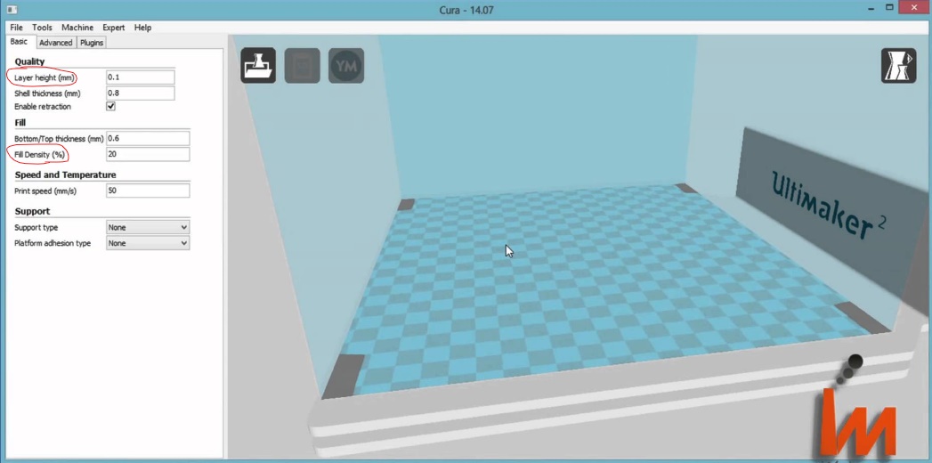
2. The next step is to import the design to a 3D printing program. For this, I used Cura. Here is an example of the Cura interface from the internet--I did not make this design.

Cura 14.07
The panel on the left-hand side has adjustable settings for several variables. The most important ones are circled and explained below:

  • Layer Height (mm): 3D Printers create 3D objects by adding one small layer on at a time. If you have taken Calculus AB, a good analogy is the step size of a line created with Euler's method. The smaller the step size, the closer the estimate will be to the real function. In 3D printing, a smaller layer height produces smoother, more natural surfaces, like a playground slide compared to a flight of stairs. The drawback of this increased quality is increased print time, because the nozzle must go over the same surface more times. 
  • Fill Density (%): This is probably the most important feature, because it determines the 3D print's durability and how much plastic it uses. For example, objects that will be under high stress need a higher fill density for added strength. To make a hollow object, set the fill density to 0%. For a solid object, set it to 100%. Anything in between these extremes will fill a percentage of the volume within the 3D print in a uniform lattice structure.  

3. Then, once the variables are set to the desired values, it is time to print! This is the 3D printer I will be using.

Note the blue "string" sticking out of the print head. 
The red part is the nozzle, where the plastic filament is applied to the 3D print.
The blue lever on the side of the print head disengages the rollers that keep the filament in place.
The bed on the bottom moves left, right, up and down to position the nozzle.
The white piece at the top holds a spool of filament, allowing the user to choose the color and quality of the filament.

I need to remove the leftover filament shown in the previous picture. Right now the nozzle is at room temperature, so the filament is stuck inside. I need to heat the nozzle to 208 degrees Fahrenheit, the filament's melting point. To do this, I use Cura's printing interface, which is, unsurprisingly, very different from a normal printer's.

Only a few of these controls are necessary to set up and operate the printer. 
First, I change the Temperature from 0 to 208 and wait for it to heat up. Then, I use the rightmost cluster of buttons to remove the filament. The EXTRUDE buttons will push the filament through the print head. Once enough filament is pushed through, I can hold down the blue lever and pull out the remaining filament from the top.

Now I can put my filament into the print head.


My algae-based, smelly filament

Fed into print head opening
The last step is to hit the print button and watch the design materialize!

Sunday, March 5, 2017

Soldering

Last week I learned how to use the soldering iron and the 3D printer at CREATE. I am going to dedicate the next two posts to explaining these in detail, and then I will continue covering my research of H-Point. Today I will show you how to solder.

What is soldering? Soldering is the process where a low-melting metal alloy is used to fuse together metals that have higher melting points. This metal alloy is called solder. Typically it is 60% tin and 40% lead, giving it a low boiling point of 188 °C (370 °F).


Solder
This is the soldering iron. When plugged in, the tip of the pen-like part gets very hot. This melts the solder from the spool onto the metals you are fusing.

(hopefully) Unplugged soldering iron
The tip of the soldering iron gets rusty over time due to oxidation. The copper mesh shown below is used to remove rust from the tip. This is known as "tinning".


I will be soldering wires from a battery holder to a motor, to make a complete circuit. The metal in the wires and the copper pads on the motor have very high melting points, but with soldering these can be joined together easily. For the motor to work, the circuit must conduct electricity, which is why you can't just super-glue the metals together.

This is the motor I will be soldering. Earlier I completed soldering the lower copper pad.

Note: Small hole for wire in copper pad
Next, I use these wire strippers to rip off the wire's plastic sleeve and expose the metal.


Then, I put the metal wire through the hole in the copper pad and twist to secure.


I have to melt the solder to close the hole in the copper pad. However, molten solder sticks to the hottest object it touches, which would be the soldering iron. To make sure it sticks to the copper pad, I must warm it up first.
Heating up copper pad/wire
Now I can introduce the solder. It will melt onto the copper pad, and some of it will vaporize into the air (probably best not to breathe in). 


Then, when I remove the soldering iron, the solder will quickly cool, creating a solid connection. 

VoilĂ !
When building my car, I will likely use soldering to connect motors like this to the rest of the electrical system. It's a very useful--and fun--tool!


Monday, February 27, 2017

Wheels and Tires

After resolving all of the design challenges involved in making a car, the choice of wheels and tires may seem like an afterthought. But in fact, they are both essential to the car's performance, and are usually considered early on in the design process.

It's also surprising how many key dimensions there are in the wheel/tire setup. For this, I'll reference a diagram from H-Point.


Most of these are self-evident. Tire crush (bottom left) is important when setting up the spindle location. If any part of the car is extremely close to the ground (like on a race car) then a little added weight could compress the tire and cause scraping on the ground, which is not good. The static load radius (SLR) solves this problem. This is a measurement of the tire radius with the occupant and maximum cargo load. The SLR determines the wheel\tire position relative to the car, because the spindle (with the rest of the car) will not get any lower than this. Thus scraping will cannot happen.

Form and function go hand in hand, so vehicles with different objectives need differently shaped wheels and tires. Trucks and SUVs have a large tire profile (aka sidewall) height to increase cargo-carrying ability (Gross Vehicle Weight, or GVW) and protect the wheels on rocky ground. This will also improve the ride comfort, because the large tires act as a cushion. However, this cushioning effect is caused by sidewall flex, in which the tire bends a little out of shape. This drastically hurts handling. Passenger cars maintain a balance between comfort and handling, Thus, these vehicles have a larger wheel and smaller tire profile. In sports cars, handling and cornering ability cannot be compromised. This requires a small tire profile to minimize sidewall flex during cornering, resulting in a larger wheel. The larger wheel also allows for a larger brake rotor, which improves braking ability. On the other hand, the larger wheel increases the combined weight of tire and wheel, which counteracts the handling benefits.

Passenger cars and light trucks have completely different tire specification methods. Lets look at an example of the former:

P 215 50 R 16

The first letter just specifies that it is for a passenger car; simple enough.

The second value is the tread width in millimeters.

The third is the sidewall aspect ratio. This is essentially the tire profile height represented as a percentage of the tread width. In this example, the profile height is 50% of 215, the tread width.

The fourth is the speed rating (not essential).

The last value is the diameter of the wheel rim.

Using these three numbers, we can determine the outside diameter of the tire.

(in millimeters) (215 x 50% x 2) + (16 x 25.4)

The first product yields tire profile, multiplied by 2 to account for the sidewall on both sides of the wheel. The second product is just a conversion from inches to millimeters. Together this adds up to the total diameter of the tire.

Thanks for reading!

Saturday, February 25, 2017

Powertrains

Finally, it's time to discuss the most important part of the automobile--the part that banished the horse-and-buggy to the history books. Of course, I am talking about the engine.

There are many different engine setups, each with their own set of advantages and drawbacks. We will explore these in a moment, but first we need to understand the system that the engine is part of, the powertrain.

Here is a visual representation of the powertrain from H-Point.


First of all, there is the engine. Conventional internal combustion engines (ICE) react fuel with oxygen to release energy that is transmitted to the wheels.

This process, naturally, starts with the transmission. Attached to the end of the engine, it can deliver power at various speeds. To do this, a clutch or torque converter is positioned between the engine and the transmission for manual or automatic transmission, respectively.

Final Drive is the series of shafts and gears that connects the transmission with the wheels, giving them power to turn.

No machine is 100% energy efficient. Unused energy is released in the form of heat, which is what makes engines hot during use. Cooling modules prevent the engine and other systems from overheating. They are placed where cool, moving air is easy to access.

The fuel tank's capacity depends on the size and intended range of the vehicle. The most important consideration is placing the fuel tank somewhere safe in case of a collision.    

The combustion reaction that occurs in the engine produces H2O and CO2. These gases must be removed so that fresh air can enter the engine. The exhaust system expels these products.

Electric Powertrains come in two forms: Battery and Fuel Cell (FC). Batteries store electrical energy while fuel cells generate it using compressed hydrogen gas.

Both use a battery, but the FC system's is a smaller, supplementary energy source.

The FC system has hydrogen storage tanks that feed the fuel cell stack.

Both systems use an electronic converter to control the amount of energy given to the motors.

Electric motors are small and powerful, which allows for easy packaging on the axle or even the individual wheels.

There is also no need for a transmission like in the ICE. However, the fuel storage tanks and batteries are much larger than a conventional fuel tank. They are usually positioned under the floor, which saves space and creates new design possibilities.

There are two ways to position a conventional engine: longitudinal and transverse.

In longitudinal engines, the output shaft is parallel to the vehicle (front-back), while in transverse engines, the output shaft is perpendicular.

Transverse engines save space, but are constrained by the width of the frame rails.
Longitudinal engines take up more space but allow for larger engines to be installed between the frame rails.

Below are all of the possible engine configurations and some examples. Notice how the placement of the engine affects the architecture.

Front engines are positioned beyond the vehicle's front spindle (the shaft that turns the wheels).

Mini Cooper
 Front mid-engines are located between the front spindle and the driver.

Dodge Viper


Rear mid-engines are located between the rear spindle and the driver.

Bugatti Veyron


Rear engines come after the vehicle's rear spindle.

Porsche 911

That's all for this week!